Automation & Control Systems
Higen Motor Co., Ltd.
28 Jan 2026
(
)
Get Your Quote Now : Quotation
Bearing application
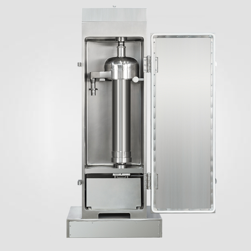
Ready Inspection and Easy Maintenance through Unique Bearing Construction
The ball and roller bearings can be greased while the motor is running. Waste grease is collected in a grease trap mounted on each end bracket. The used grease is removed with a single stroke of the discharge handle, simplifying inspection and maintenance. In frame sizes 500 or above, roller bearings at each end absorb radial load, and ball bearings at the drive end absorb thrust load. This assures stability and longer life.
Sleeve bearings employ efficient sealing between shaft and bearing to prevent lubricants from leaking either into the motor housing or outside the housing. The sleeve bearings are split into two halves. Removing the upper half exposes the bearing interior. Bracket removal is not required for inspection or maintenance.
Type | BD,BS-O,ME | HE |
Pole | 4-Pole
or more | 4-Pole | 6-Pole | 8-Pole |
Frame |
400 | Ball or roller bearings
(Grease lubrication) |
450 |
500 |
Bearing application of motors in 4-pole or more is listed above. |
Ball
or
Roller
Bearing | Frame
450
or
below | |
Frame
500
or
above | |
Sleeve
Bearing | |
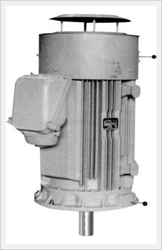
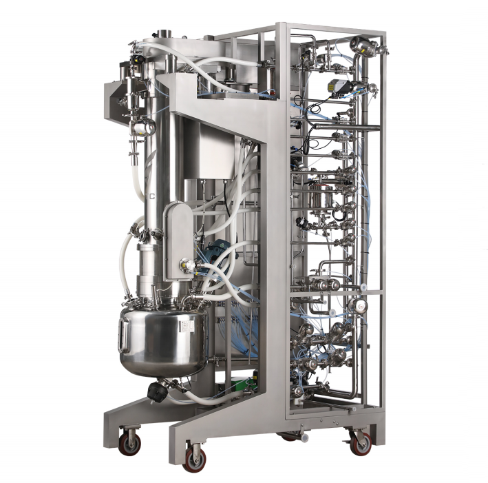
HIGEN Motor Totally Enclosed Fan Cooled Vertical motors are designed to IEC dimension.
As the apparatus is built with the main body that is totally enclosed, and cooled by a cooling fan on the opposite drive end, it allows direct installation of a counter apparatus on flange part by using it as a linkage axis bracket.
It ensures a full performance of its advantage as motors for Machine tools, Pumps, Centrifuges etc.
Often committed in dusty and humid environments. |
Type FEV-0 55kW 4p
|
RATINGS AND SPECIFICATIONS
Standard Out put Ranges : See Table 1Types and Starting Torgue.
TYPE FEVK - Squirrvel-Cage, Starting 100% or above full-load torgue.
TYPE FEVF - Squirrvel-Cage, Starting 150% or above full-load torgue.Time Rating : continuousRated Vottage : 6000V 50Hz, 6600V 60HzInsutation : Class FAllowable Temperature rise : 100a?? (by resistance method)Bearings : Regreasable ball or roller bearingsNO.of Motor Leads : 3Connection to Load : Direct drive.Finish in munsell Notation : 5PB 8 / 2.5(Blue)<Table1> Standard Output Ranges
1. Motors cannot carry thust losd from driven machine.
2. Motors other than thse listed above are available. |
<Table2> Characteristics
Voltage | Pole | Output
(kw) | Frame
FEV | Full-load
Current (A) | Full-load
Pole Speed (rpm) | FEVRotor
GD2
(kg·m2) |
50 (Hz) | 60 (Hz) | 50 (Hz) | 60 (Hz) |
High
Voltage | 4 | 90 | 280 MBS | 22 | 19.5 | 1475 | 1775 | 6 |
110 | 280 MBS | 26.5 | 24 | 1475 | 1775 | 7.2 |
132 | 315 MBG | 31.5 | 28.5 | 1480 | 1780 | 11.2 |
160 | 315 MBG | 37.5 | 34 | 1480 | 1780 | 13.2 |
200 | 355 MBG | 46.5 | 42 | 1480 | 1780 | 17.2 |
250 | 355 MBG | 58 | 52 | 1480 | 1780 | 21.2 |
315 | 355 MBG | 72.5 | 65 | 1480 | 1780 | 33.2 |
6 | 75 | 280 MBS | 20 | 18 | 980 | 1180 | 6.4 |
90 | 280 MBS | 23.5 | 21 | 980 | 1180 | 7.6 |
110 | 315 MBG | 28.5 | 25.5 | 980 | 1180 | 12.0 |
132 | 315 MBG | 34 | 30 | 980 | 1180 | 14 |
160 | 355 MBG | 41 | 36.5 | 985 | 1185 | 18 |
200 | 355 MBG | 51 | 45 | 985 | 1185 | 23.2 |
250 | 355 MBG | 62.5 | 55.5 | 985 | 1185 | 35.2 |
8 | 37 | 280 MBS | 11.5 | 10 | 735 | 885 | 5.6 |
45 | 280 MBS | 13.5 | 12 | 735 | 885 | 6.8 |
55 | 280 MBS | 16.5 | 14.5 | 735 | 885 | 7.2 |
75 | 280 MBS | 21.5 | 19 | 735 | 885 | 9.6 |
90 | 315 MBG | 25.5 | 22.5 | 735 | 885 | 14 |
110 | 315 MBG | 30.5 | 26.5 | 735 | 885 | 19.2 |
132 | 355 MBG | 36 | 31.5 | 735 | 885 | 21.2 |
160 | 355 MBG | 43 | 38 | 735 | 885 | 27.2 |
TERMINAL BOXES AND POWER LEAD SIZE
Shown in the table 3 are standard application of terminal boxes to motor output and applicable lead size to the terminal boxes.
<Table3> Terminal Boxes and Power Lead Sizes
Motor Ratings | Sectional Area
of Power Lead
Conductor
(mm2) | Terminal Boxes
Motor Ratings (Made of Steel Sheet) |
Voltage
(V) | Output
(kw) | Type | Power Lead
Entrance | Dwg
No. |
High
Voltage | 3000 | 37 to132
160, 200
250
315 | 14 (Three-core)
22 (Three-core)
30 (Three-core)
50 (Three-core) | KU-
300F | An entrance
cover with
7mm dia
hole is
mounted | 1 |
CONSTRUCTION OF TERMINAL BOXES
<Drawing1>
DIMENSIONS in mm
Two types of the bearings are used for a motor.
Single-row cylindrical roller bearing are employed at drive end. Single-row deep-groove bearings are employed at opposite drive end. Motor is equipped with a short shaft extension for a direct-connected drive as standard.
Frame. FEV- | Flange
No. | LA | LB | LC | LE | LG | DC | DD | KL | LL | LR | L | LZ |
280 MBG | FE 600 | 600 | 550 js6 | 660 | 6 | 25 | 725 | 640 | 560 | 1170 | 170 | 1340 | 24 |
315 MBG | FE 600 | 600 | 550 js6 | 660 | 6 | 25 | 780 | 690 | 590 | 1270 | 170 | 1440 | 24 |
355 MBG | - | 740 | 680 h7 | 800 | 5 | 25 | 860 | 750 | 630 | 1510 | 170 | 1680 | 24 |
Frame. FEV- | Flange
No. | Shaft Extensin | Bearing No. | Approx.
Weight
kg |
Q | QK | QR | S m6 | T | U | W | PC | XE | XL | Drive
End | Opp
Drive End |
280 MBG | FE 600 | 170 | 140 | 1.2 | 85 | 14 | 9 | 22 | 50 | M 12 | 20 | NU 318 | 6318 C3 | 930 |
315 MBG | FE 600 | 170 | 140 | 1.2 | 95 | 14 | 9 | 25 | 63 | M 16 | 27 | NU 320 | 6320 C3 | 1190 |
355 MBG | - | 170 | 140 | 1.2 | 95 | 14 | 9 | 25 | 63 | M 16 | 27 | NU 320 | 6320 C3 | 1800 |
1. Dimensions of the shaft extension key and keyway are based on KS (Korean Standard) B 1311 "Sunk keys and Their Corresponding Keyways."Shaft extension key is furnished
2. Tolerances on dimension LB of flange diameter and S of shaft extension diameter are based on KS B 0401 "Limits and Fits for Engineering."
3. Approximate motor weights are of maximum motors.
4. Terminal box can be turned to one of four positions, 90 degrees apart to provide easy entrance of the power leads. |


Clients Reviews